
How to Reverse Engineer Undocumented PLC Programs

You show up on a new integrator job. The Original Equipment Manufacturer (OEM) who built the line is unreachable. The panel drawings are stale. With some luck, you download the project file from the production PLC, but there are zero comments, the tags are just raw memory addresses, and you are left staring at thousands of rungs of undocumented Ladder Logic.
Every controls guy has inherited a program like this. No comments. No I/O list. Maybe it has function block diagram (FBD) that doesn't make much sense, or structured text with blank headers on top. Naturally nobody on site remembers why certain tags gate the whole line or what communication protocols are used across the devices.
This undocumented PLC program is a production liability. A technical debt that needs to be addressed before becoming a huge problem.
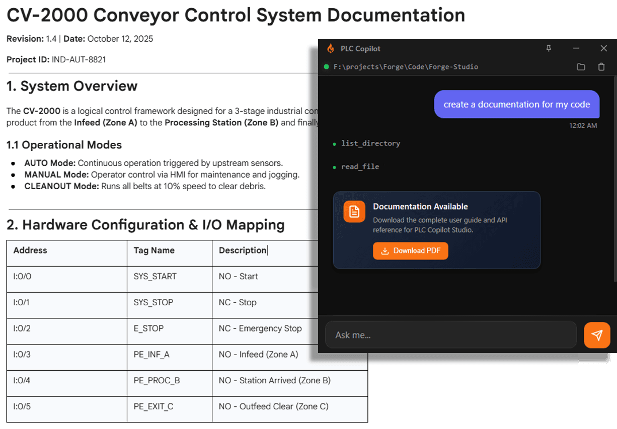
How to Document PLC Program
"Undocumented" doesn't necessarily mean that nobody has ever written anything about the project. It simply means that the information provided is not enough. On legacy PLC code it's usually the stack up of the following:
- No rung comments on the sequences that matter
- Cryptic tag names and alias chains many levels deep
- Confusing tag descriptions
- ST routines with outdated comments
- Missing or wrong I/O documentation
- Lost project history
With some older PLC brands, the rung and tag comments are not stored in the PLC controller. They live in the project file. If the original project file is lost, there's no way to recover the original comments from live PLCs.
For a system integrator this happens more often than it should. Inheriting unfamiliar logic on a tight schedule. The in-house engineer who knew the quirks retired. You know how blame works when something trips on a running line. It's not an easy task to convert a spaghetti code into a maintainable project for production.
The Pre-AI Reality: The PLC Reverse Engineering Grind
Before AI tools like PLC Copilot existed, deciphering an undocumented PLC project was a brutal, time-consuming test of patience. If you were the engineer stepping into that scenario, your reverse-engineering workflow probably looked exactly like this:
- Finding the thread: You would scroll through the project tree to pick a logical starting point, usually hunting for the Main routine or the primary sequence routine just to establish a baseline of how the machine cycled.
- The cross-reference rabbit hole: Once you found a critical tag, the manual detective work began. You had to manually cross-reference every important variable, tracing it through countless rungs, subroutines, and add-on instructions to figure out its origin.
- The Excel spreadsheet map: Manually logging every tag's source and destination in a spreadsheet just to rebuild the missing data dictionary.
- Leaving breadcrumbs: As you slowly pieced the logic together, you would add or update rung comments one by one. You were translating raw logic into human-readable notes just so you wouldn't lose your train of thought the next day.
If you were lucky, after a week or two of this agonizing manual labor, the project's architecture would finally click into place.
Only then, after losing at least a week of valuable engineering time, could you actually begin the real work of editing, troubleshooting, or upgrading the code.
Dedicated AI Tools for Legacy PLC Documentation: Reverse Engineer Ladder Logic and Function Block Diagram
Not all AI is built for control systems. General-purpose LLMs like ChatGPT or Claude can analyze text, but they lack deep domain knowledge of industrial automation. Purpose-built tools like PLC Copilot on the other hand, they are engineered specifically for control logic. Instead of relying on variable names, PLC Copilot evaluates the actual underlying execution path across Ladder Logic, Structured Text, and Function Block Diagrams. The workflow is vendor agnostic, so the same reverse-engineering and documentation flow applies whether the project lives in Rockwell Studio5000, Siemens TIA Portal, or CODESYS. Even if tag names are cryptic (B3:0/1 or Tag_1024) or existing rung comments are completely outdated and wrong, the AI parses what the logic physically does to provide precise explanations.
One engineer who uses PLC Copilot on jobs like this put it plainly:
"I fed the project into your Copilot and started asking questions about what subroutines are doing. The results are a lifesaver and have cut down the reverse engineering time significantly."

PLC Documentation Automation, Exporting Documents as PDF
Once the AI unravels a legacy project, you need a way to present those insights to team members or clients. PLC Copilot lets you generate clean, professionally formatted PDF or CSV documentation with a single click. Instead of spending hours pasting screenshots and text into Word documents to create turn-over packages, you get standardized, print-ready reports covering project structures, sequence breakdowns, and routine summaries.
AI to Generate Rung Comments and Tag Descriptions
Eliminate the tedious task of typing out descriptions line by line. PLC Copilot analyzes what each rung and instruction accomplishes and automatically generates clear, context-aware tag descriptions and rung comments. Instead of just stating what the code is (e.g., "Turns on Output 3"), the AI explains the intent behind the logic (e.g., "Energizes main lube pump starter when system pressure drops below 30 PSI for 5 seconds").
Linked to Your Organization's Knowledgebase
Documentation is only useful if it fits your company's specific way of working. PLC Copilot connects directly to your organization's internal standards, site manuals, and historical project repositories. This means the AI doesn't just generate generic descriptions, it uses your team's preferred naming conventions, acronyms, and standard operating procedures to keep all code and documentation consistent across every plant and project.

Why Does Documentation Matter?
When a line goes down, every minute costs money and bad documentation turns a quick fix into an expensive problem.
Troubleshooting is only half the story. Proper documentation is the backbone of a resilient operation. It accelerates onboarding for the next engineer, enables seamless collaboration across different teams, and provides the exact context needed for accurate work instructions and critical safety notes. Without it, plant knowledge walks out the door whenever a senior tech retires.
When that documentation is missing, legacy code becomes a nightmare. You fight through alias chains that hide the real bit, nested Add-On Instructions (AOI) where you have to drill down one layer at a time, and the same interlock pattern copy-pasted under completely different tag names. Worse, critical mode logic is often split across five different routines without a single overview comment, forcing you to re-discover the same permissive over and over again.
How to Properly Document a PLC Program
Good documentation isn't about describing every single contact; it’s about explaining intent. Here is the framework for doing it right:
- Document the "Why," Not the "What": Don't write
XIC Input_1 turns on Output_1. WritePressure switch feedback energizes main lube pump. Anyone can read the syntax; comments should explain the physical machine behavior. - Provide High-Level Routine Overviews: Add a header block at the top of every routine outlining its core responsibility, execution trigger, and dependencies before diving into individual rungs.
- Map the State Machine: If a routine controls a sequence, document the step numbers, transition conditions, and fault recovery paths in one central summary comment.
- Name Tags Contextually: Avoid generic labels. Standardize tag names and descriptions so any engineer can identify signal origin, function, and destination at a glance.
Before You Hand Off the Line
Documentation isn't just for reverse-engineering legacy projects. It is the final, critical step of handing over a new one.
When you complete a commissioning project, leaving behind clean, standardized documentation is what separates a professional integration job from a future nightmare. Clear comments, generated tag descriptions, and a documented control narrative protect your team from middle-of-the-night support calls and ensure the client's plant engineers can safely maintain the machine long after you pack up your laptop.
Essential Controls Engineering Documents
When managing, upgrading, or handing off a control system, several types of documentation come into play. Here is a breakdown of the standard documents every controls engineer should know:
| Document Name | Description |
|---|---|
| Control Narrative / Sequence of Operations (SOO) | A plain-English, step-by-step description of how the process or machine is supposed to run, including start/stop conditions, interlocks, and failure modes. |
| Cause & Effect Matrix (C&E) | A grid mapping specific process conditions or alarms (the causes) to the required automated system responses (the effects). Crucial for programming safety interlocks and shutdown logic. |
| I/O List | The master spreadsheet mapping every physical and network Input/Output point to its respective instrument, PLC address, tag name, and data type. |
| Piping & Instrumentation Diagram (P&ID) | The foundational schematic showing the physical process flow, piping, vessels, and all connected sensors and actuators. |
| Electrical Schematics & Panel Drawings | Detailed wiring diagrams showing power distribution, grounding, terminal blocks, safety circuits, and physical panel layouts. |
| Functional Design Specification (FDS) | A highly technical document detailing exactly how the control system software and hardware will be engineered to meet the project requirements. |
| Network Architecture Diagram | A visual map of the industrial IT/OT network, showing PLCs, HMIs, switches, drives, IP addresses, and communication protocols (e.g., EtherNet/IP, PROFINET). |
| FAT / SAT Protocols | Factory and Site Acceptance Test documents containing the strict checklists and procedures used to validate that the system safely works as designed before and after installation. |
| Operation & Maintenance (O&M) Manual | The comprehensive guide left for the plant floor, containing operator instructions, troubleshooting steps, spare parts lists, and preventative maintenance schedules. |
Frequently asked questions
Still comparing tools? Best AI agent for PLC programming lays out specialized agents vs raw ChatGPT on real IDE workflows.